Designing a programmable sound generator board, part 2
If you haven't read the first part, where I introduce the idea and architecture, I highly recommend reading it before continuing.
Since making the first prototype of my PSG, I didn't make any changes to the board, or even use it much at all. I was completely burned out after the 12 hour soldering session, and I did not want to have to do it again (even if I now knew how to speed it up a bit). Furthermore, I knew that at some point I'd eventually get a proper circuit board printed, and all work on the prototype would be obsolete after that happened. Finally, the wires I had connected to the Pico were very fragile, unprotected, and not organized in a way that would let me pull the Pico out cleanly. These all combined with the fact that I had other more important things to do during the summer (like finishing Phoenix), which meant that I had no time to make any progress.
Even though I had a PCB prototype designed, I avoided actually getting it printed for a long time. This is because the board I designed was four layers deep. I did this because I believed that it was not possible to connect all the traces to all 18 chips using only two layers. The manufacturer I wanted to use, JLCPCB, wanted $40 for a set of 5 boards, and this was a bit too much for me at the time, so I didn't get the board printed.
In addition, this summer has been my busiest yet, as I was preparing to move to college, which meant putting away tons of parts, tools, and wires, and just generally cleaning up ahead of my departure. Once I moved out, I had very few electronic parts with me - I only had the Arduino I used as an adapter for my keyboard, and the Raspberry Pi I used to build packages for ARM Linux. This kept the project out of my head, as I wasn't fiddling with electronics for hours anymore.
However, this all changed around the beginning of October. One day, I was walking around, stretching my legs after being at my desk for hours, and a random thought popped into my head.
Why did I put the frequency multiplication code on the slow, time-sensitive PIC chips, and not on the fast, time-insensitive Pico?
This thought possessed my mind for the rest of the day. Wow, that was really a stupid move. I've gotta fix that - it'll make my code so much better. As soon as I had a moment, I opened up the assembly code for the first time in many months, and adjusted the code to save the input directly instead of running the multiplication. Then I updated the Pico's code to move the multiplication there, making it send the precomputed increment instead of the frequency.
Unfortunately, I did not have the board with me to test with. So, as any normal person would, I decided to write an entire emulator for the processor. Two days and 1000 lines of C code later, I had a working emulator that could load the hex files that the compiler output, and I was able to verify (mostly) that the code worked properly.
Meanwhile, I wanted to revisit my PCB design to see if there were any optimizations I could make. In particular, I wanted to adjust it so that a) there were full ground and V+ planes on the surfaces, b) the interrupt and Pico signal traces were on their own separate layers (previously, they were mixed across layers), and c) the traces were just generally cleaner. I started to work on it a bit, but eventually I realized that I needed to remap all of the pins and traces to use "nets" (groups of pins that all connect together) if I wanted to have proper planes. To fix this, I rewired the entire board, mapping all 288 pins to the required nets before placing the traces. Then I placed some rectangles to create the ground and V+ planes, and filled them in, which now worked correctly, avoiding all traces except for the ones they were connected to.
Once that redesign was done, I checked the price of the PCB again just in case something changed, but it was still $40. At that point, I figured that the price was likely due to the fact that I was still using a four-layer board. I continued redesigning the board by removing the middle two layers, instead trying to route the middle traces across the horizontal bus traces on both layers. I had been avoiding this both for simplicity of design and because I was afraid of using too many vias (not quite sure why), but after a few hours of rewiring I had a fully connected two-layer board. I uploaded this version to the PCB website, and discovered that the board was only $5! At that point, I decided it was worth it to finally build the full circuit board.
Because I already had most of the chips I needed, I only bought eight more PIC chips to complete the set of 16 alongside the eight I had from the prototype. I also needed an extra shift register chip for those eight chips. However, I couldn't reuse any of the sockets from the prototype, so I bought all new sockets for those. Finally, I got some female pin headers for the Pi Pico to slot into, instead of relying on loose wires as the prototype did. The total price for all those parts was about $30 - if I'd bought all of the parts required, it would come out to about $45.
Before ordering everything, I checked over the board multiple times to really make sure that I had everything right. I adjusted some of the traces to be a bit more clean, and also changed the color of the board from standard green to a nice purple that both looked great and had very visible traces. Once everything was checked over and complete, I placed the order, and waited for the board to arrive - estimates from the manufacturer said about 3 days for production, plus 2-4 weeks for delivery.
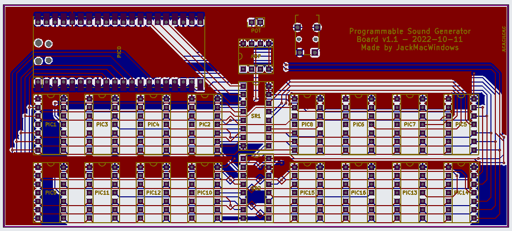
The PCB schematic as I sent it for production.
While I waited, I went back to the software to see if there were any major things I could do to optimize it. One big concern I remembered from the initial design was that I had a lot of trouble relating to transfer speeds. When I tried to play some 8- or 16-channel modules in tracc, I experienced a lot of slowdown issues on particularly heavy rows. These modules never gave me any issues when played using the native sound plugin, or even with software sample-based playback. I discovered that a potential bottleneck for transfer speeds was likely in the speed of the USB serial protocol. Even when I changed the baud rate of the port to different speeds, it was still stuck running much slower than I needed. I had tried using different methods to try to batch the data transferred, but nothing managed to work quite well enough, and it only made my code much messier than it needed to be.
To try to solve this issue, I first looked at writing my own USB protocol to transfer the data. I poked around at using libusb and TinyUSB (the Pi Pico SDK's built-in USB stack) to send data using the same protocol I was using over serial, but directly. However, I eventually came to a realization that there was likely a protocol that already existed with enough features for me to be able to use. Then it hit me – that protocol I was looking for was MIDI, which is specifically intended for musical instruments, and has plenty of commands to be able to not only directly control the PSG's parameters, but also add effects to the music and other system controls. Another really cool benefit was that it could become an actual synthesizer device, able to play back MIDI files and be plugged into digital audio workstations like Garageband. This sounded really cool to me, and I got to work rewriting my entire Pico driver around the MIDI protocol.
Up to this point, I'd rarely used TinyUSB directly on the Pico. My only experience was through the USB standard I/O package that the Pico SDK added to be able to use C printf and other functions to send serial data. I'd also once tried to use the host stack to allow using a keyboard with the Pico, but I never got it to work properly. In addition, TinyUSB didn't have much documentation at all about how to use it or what functions it provided, so I had to copy from the examples and try to piece together what they did.
TinyUSB's MIDI support consists of a few functions to read and write MIDI messages, as well as some callback functions for when packets are received + device connect/disconnect notifications. For the first version, I avoided using any of the callbacks and instead opted to run everything in the main loop. The loop would run the TinyUSB device task to fetch packets, and then for each packet received it decoded them and then executed the instructions directly. One issue I ran into real quick is that the message reading function didn't have any indication as to how the data was stored - it just wanted a four-byte buffer - so I assumed it was a normal MIDI message, with the first byte being the status, and the other two were parameters. To clean it up, I made a four-byte structure that named each byte with what it did. But when I started testing it, the commands were giving me random data. After throwing it in a debugger, I discovered that the actual message started on the second byte - the first byte appeared to be junk, so I moved the junk byte four up to the first byte instead, shifting the names down by one. (After reading the USB MIDI protocol standard, I discovered that this byte was a special indicator that held some metadata to help players. This byte stored information such as the "cable number", which allows more than 16 channels on one cable, and whether the stream contained a SysEx command.)
The command parser was very simple: it used a bunch of switch/case statements to select how to modify the playback. The main statement switched over the primary status command, which was the first four bits of the status byte. To make the board at least base-level compatible with MIDI, I implemented all of the commands properly, including note on/off, pitch bend, aftertouch, program change, and as many control change settings as I could. I also added some features to be able to control the board with direct commands to the PSG components, which included direct frequency and volume adjustment control change wheels for each channel. Since the chips could only play one note at a time, while MIDI could play multiple notes at once, I needed to have some code to automatically reassign channels when multiple notes are being played. I also implemented a mode change to be able to swap the synthesizer code between MIDI mode (which can play multiple notes per channel & reassigns chips as needed) and PSG mode (which has exactly one chip per channel, so one note per channel). Luckily, MIDI already had a monophony/polyphony switch assigned to two control change wheels, so I used those to control which mode the board was in.
On the PC side, I also rewrote the CraftOS-PC plugin to use MIDI instead of serial. This involved learning how to use the PortMidi library, which is a simple cross-platform API for interacting with MIDI devices. I adjusted the functions to send MIDI events instead of using my custom serial protocol, which appeared to work from just reading it over, but I knew that some issue would pop up once I was able to test it on the real device.
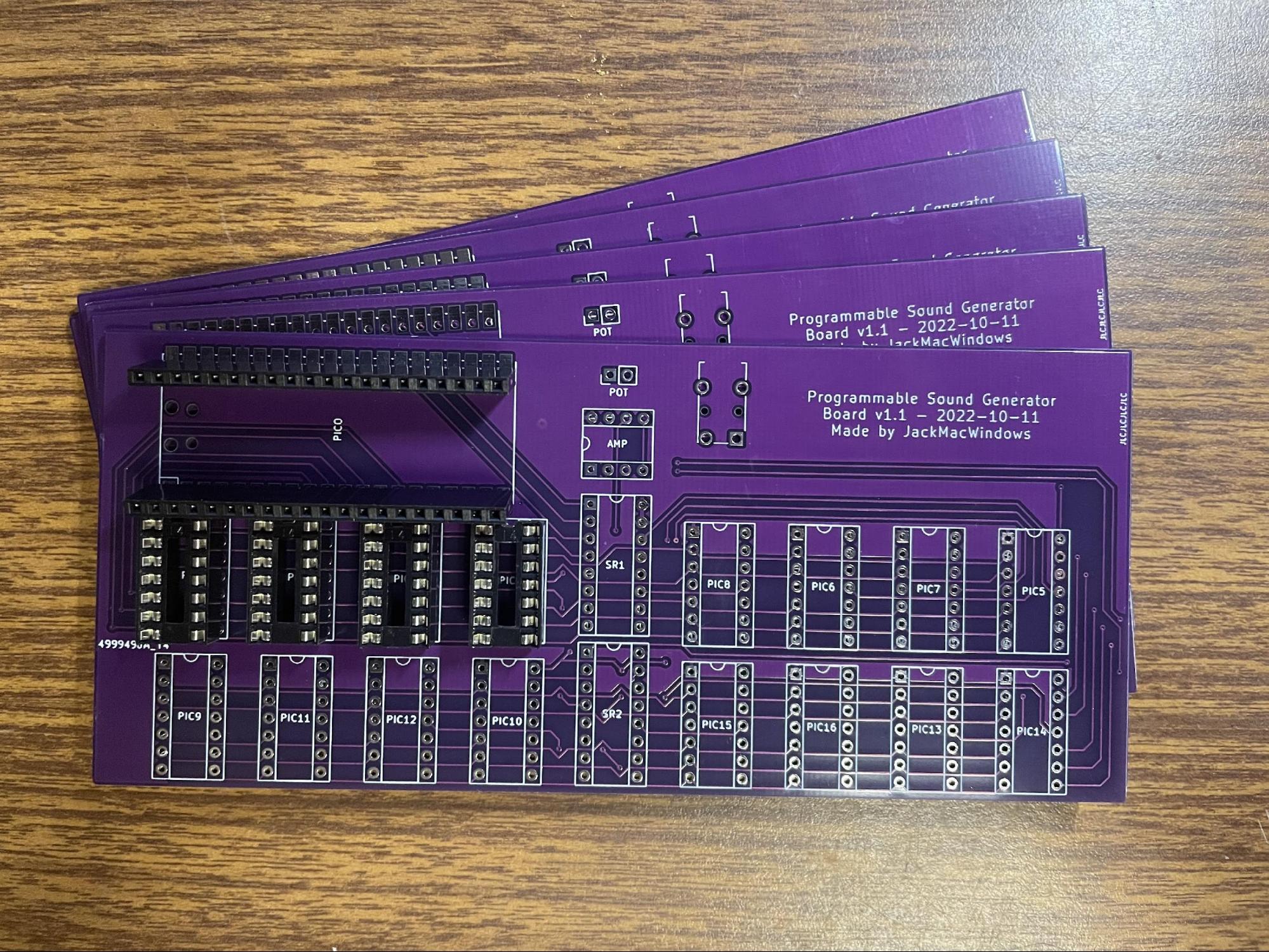
The circuit boards, bare and unpopulated (mostly).
By the time I finished writing the first MIDI code, the boards arrived from China – they were at my doorstep in just over a week, which was way faster than I expected. I'd already received the other parts I needed during that time, so everything was ready to go. After taking a few hours to inspect the boards and just generally feeling happy about finally getting my own boards fabricated, I scheduled an appointment with the local Makerspace's soldering iron, and got the stuff I needed together in preparation.
I went into the Makerspace with a backpack full of all of the parts I needed, including the PCB, the sockets, the chips, and my Pico and prototype board, which I had just picked up from home the day before. I sat down at the soldering station, and proceeded to unpack all of my materials before starting. I started by attaching the sockets for each chip - 19 sockets in total, with 264 pins to solder. It took me about half an hour to get through all of those pins, and, once the board was heated up a bit, each joint went together as smooth as butter. After that, I added the header for the Pico - 40 pins combined - and that went pretty well; though I did end up with one of the headers at an angle, so I had to use a bit of force to bend it to fit.
Then I moved onto the headphone jack. I had very few of these, and I wanted to reuse the one I had on the prototype to avoid having to find more. It also happened to be one of the only jacks that had a footprint built into the PCB designer. So first, I had to desolder the port from the old board. At first, I thought this wouldn't be too hard, but after a few minutes of attempts, I was unable to get all of the solder out of the hole. I did have both solder suckers and wick at my disposal, but neither of these were effective enough to get all of the solder out. After over half an hour of trying to get it out, I eventually managed to just barely rip it out of the board, though there were pads from the breadboard still stuck on some of the pins. I figured this wouldn't be much of an issue, but as soon as I tried to push the jack into the board, one of the pins inside the jack bent way out of shape. I tried to helplessly get it to go back to normal, but after much more struggling, it eventually became unsalvageable, and I just ripped the entire thing out in search of a new solution. Luckily, there happened to be a piezoelectric beeper in the spare parts bin next to me, and I made a split-second decision to add that instead. (Little did I know that that decision would be a serious problem in the future.)
Fortunately, I managed to get the potentiometer for volume control off of the original board (with a tiny last-minute hack after I tore one of the traces off of the pot's carrier board), and I added that on last. Once it was all together, I hastily added the chips onto the board, plugged in the Pico, and tried to test it out. I didn't have my development PC with me, so I was only able to test out the MIDI functionality, but I was unable to get any sound out of it. Because I was already running over an hour over my appointment time, and I didn't have enough stuff with me to properly debug it, I collected the assembled board and leftover parts, and headed back home to do further testing.
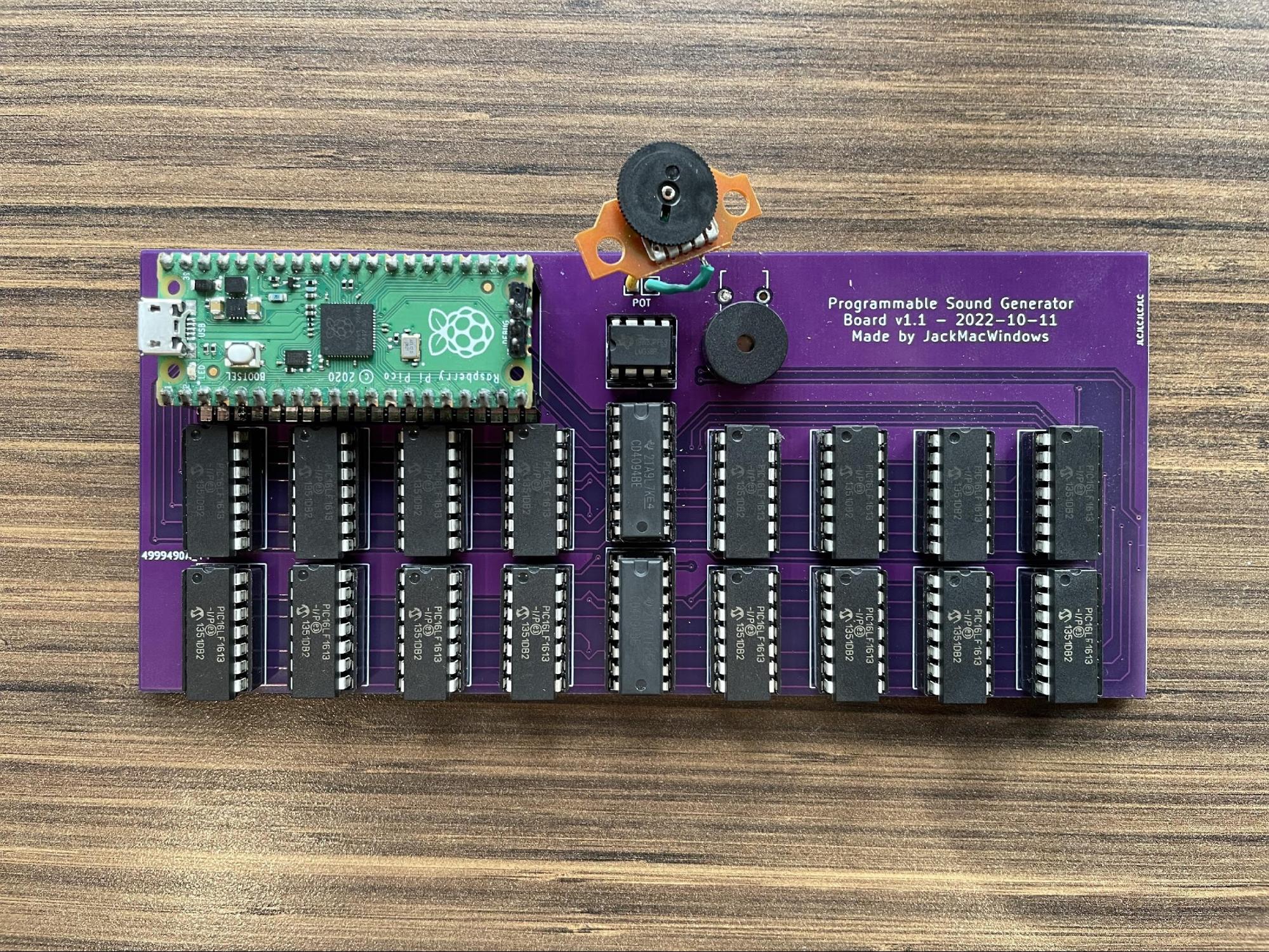
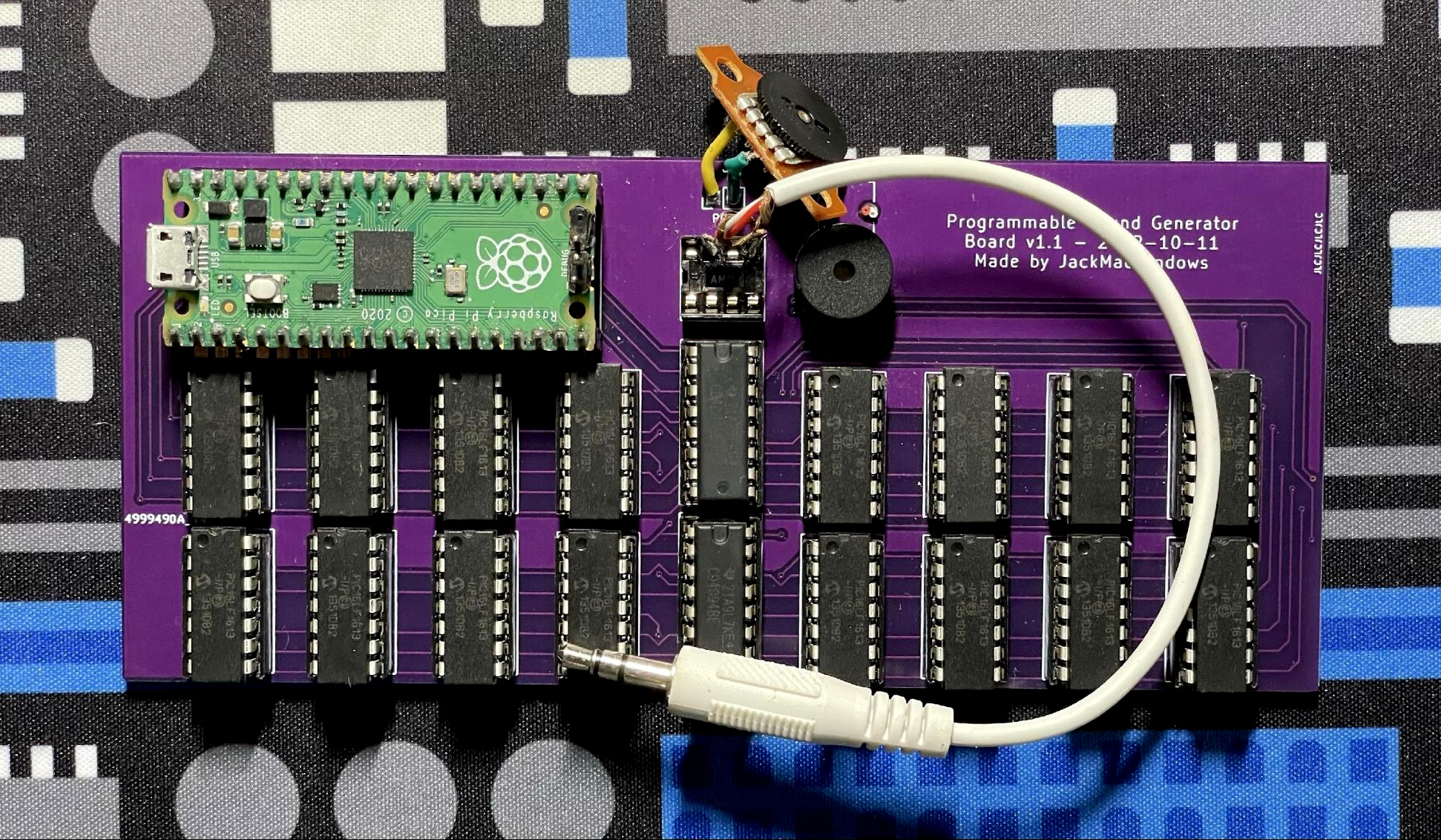
The assembled board with all chips socketed.
I was expecting the debugging process to be a bit of a pain, but I completely underestimated how much pain I was about to go through. The first issue I had to wrangle with was a complete lack of output. At first, I thought it was an issue with the MIDI code, but I kept tweaking it and trying to find issues, but I didn't find any. To really make sure it wasn't a MIDI issue, I completely restructured the code to send commands differently - instead of actively looking for MIDI packets in the main loop, I moved to using the callback functions that TinyUSB provides. After that change, the main loop was simply calling the TinyUSB update task infinitely. I also moved the output code into its own loop on the second core, which allowed me to batch commands effectively, as well as run effects like volume release/fade out (though this wasn't implemented until much later).
Even with this change, I couldn't hear anything at all. As a last resort, I decided to wire up a speaker cable instead of using the beeper, and turned up the volume on my speaker to maximum to see if it was too quiet for the beeper. Well. It turned out that it was working, but the output was just extremely quiet. I was a bit confused about it, but figured it was likely a result of me not wiring the op amp correctly. To confirm that, I tried removing the op amp. Just a few weeks before, I learned in one of my college classes that the op amp was actually unnecessary to combine the signals - the linearity property of electrical circuits causes parallel voltage sources to add together, which is exactly what I'm dealing with. However, adding 16 voltage sources that go up to 3.3V (1.6V when silent) could reach voltages in excess of 50V! This is not safe for audio equipment at all. The op amp's function was also to reduce the voltage to a safe level for audio equipment. Pulling out the main component that was limiting the voltage was a bit scary, but I did it anyway.
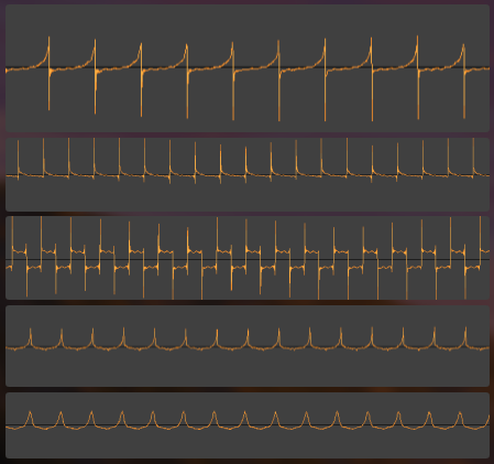
It turned out the potentiometer I used for tuning the op amp had the perfect resistance to drop the voltage to a decent level, and I got an (ear-bustingly loud) wave to output from the speaker, though the wave was still too quiet for the beeper. However, it sounded really odd - my square wave was super noisy, my sine wave sounded like a terrible triangle wave, and my triangle wave was just blips. I was really confused as to why this was happening, so I plugged it into my PC to try to see the output waveform through Audacity. I discovered that the waveforms were massively distorted for some reason.
The waveforms I was getting. From top to bottom: sawtooth up, sawtooth down, square (50%), triangle, sine.
To try to analyze this issue, I went to my college's engineering lab to analyze the inputs and outputs using an oscilloscope. After setting up the workstation - the oscilloscope was over 20 years old and ran Windows 98! - I started probing around to try to find the voltages. But the scope was very uncalibrated, giving me wildly inaccurate measurements, and I had no idea how to work the thing - I'd never used an oscilloscope before this, and I was especially inexperienced with scopes that ran Windows and used a keyboard and mouse to configure settings. After some poking around, I was able to find the calibration menu, and I was able to get it measuring my circuit properly.
I first checked the voltage of the initial output rail connected to all of the chips, and confirmed that it was outputting about 25V when silent. I also found that the waveform was correct! I then checked the voltage coming out of the op amp, and found that not only was the output ridiculously low, it also had the same weird shapes. Eventually, I had a realization: the beeper module I added was acting as a capacitor, and was affecting the shape of the speaker cable output. This is (probably) because the piezoelectric component is made with two electrodes that have a piezoelectric insulating material between them, which is how a capacitor is constructed. Adding a voltage output in parallel was taking the voltage across the beeper, which, as I learned later on in the college class, was equal to the integral of the current. This ended up affecting the shape pretty badly.
Note: Ok, I'll admit that I'm not entirely sure the exact reason why the shape was affected - the characteristics of the beeper are still a bit of a mystery to me, and I'm not quite 100% solid on the class material yet. However, the appearance of derivatives in the waveforms does appear to line up with my theory - it's just a bit hazy how exactly they connect together, especially as derivative voltages are more consistent with inductors... which would match with a normal speaker instead.
To resolve the issue, I cut the trace connecting the speaker, and tested it out. Lo and behold, the output sounded great. After fiddling with a few more things, and putting all of the chips back in (as I had been testing with only one at a time), I tried it out with an 8-channel module. Besides some volume inconsistencies, it was beautiful.
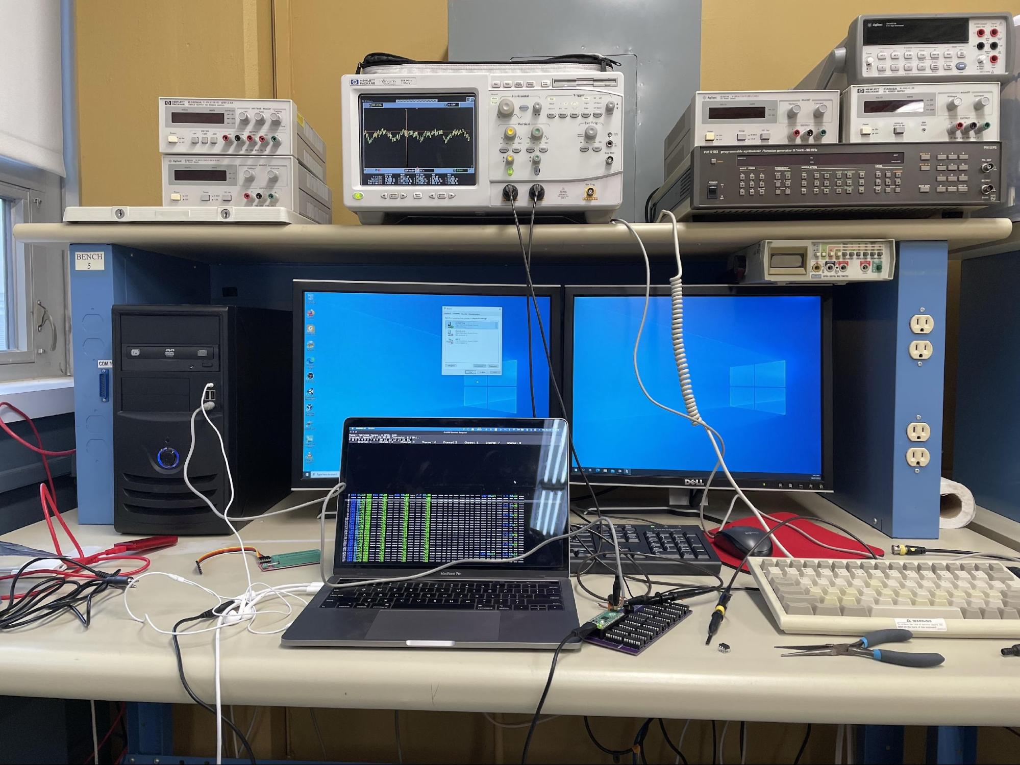
My oscilloscope workstation while playing the 8-channel module.
At this point, the board was working well enough for many songs to play. However, I was still facing a number of minor issues that caused glitches in the audio. First of all, the sine waves sounded much louder than the rest of the wave types when playing some of my songs. Normally, pure sine waves sound quieter than other sharper wave types, so I account for that by boosting the volume of the sine instruments. However, for whatever reason the sine wave was about as loud as the other waves, so it was overpowering everything else in the song. It also sounded like the loudness increased much quicker towards the higher volume levels. To fix this, I implemented a logarithmic equation to make the volume increase slower as it goes higher. This solved my volume scaling issues, though it did make volume jumps from 0 to 1 much more noticeable.
The other issue I was facing was much more serious than the volume glitch. Very occasionally, some songs would completely miss some notes or effects. These misses were always in the exact same location, but I couldn't figure out what pattern the misses were happening in. I spent multiple days scouring my code to figure out what the cause could be - I rewrote the code a few times, added various pauses in case it was a timing issue, and even ripped out all of the chips to test each channel one-by-one. After nearly a week of squeezing my brain into paste to find the bug, I finally found the reason: I never cleared the chip selector after sending a command. This meant that when two commands were sent to the same chip without any other chips being updated, the wire that tells the chip that a new command didn't pulse - it just stayed on as it was before, and thus the chip never went into command selection mode. To fix this, all I had to do was tell the shift register to update its output after clearing the memory, which actually reset all of the pins to zero, letting new signals generate pulses again. Once this bug was fixed, the board sounded perfectly as I wanted it to.
But I wasn't done coding yet.
Having to rip out each and every chip to reprogram them was getting pretty annoying - it took at least 5 minutes and around 10 bent pins each time to do one reprogramming cycle. I was getting fed up with this labor-intensive process - I'd only been programming four chips at a time while testing to avoid having to rip out all the others. I wanted to add an In-Circuit Serial Programming (ICSP) port to my board to make this easier; however, ICSP is a two-way protocol, and having every pin of each chip connected together would cause interference (and high voltages!) while every chip sends its own signals out. I wanted to find an alternative to ICSP that would allow me to send one-way firmware data to every chip at the same time.
While searching, I came across an article talking about programming microcontrollers, and in it they mentioned that people usually program their chips with a bootloader first, which then handles writing the code to memory from a more convenient location. Duh! I could write my own bootloader using the same 8-bit bus connected to the Pico! I started reading the documentation for writing to the flash code memory on the PIC, and after a few hours I had a basic bootloader (written in assembly) that could accept HEX-formatted firmware from the 8-bit bus and write it to the flash. To send the data, I added a SysEx command on the Pico's MIDI interface that takes a whole HEX file, adjusts it into a consistent format for sending to the PIC chips, and then selects every chip at once and sends an FF 01 command with the firmware data.
After adding the firmware update command, I wanted to streamline uploading firmware updates to the device. To do this, I wrote a simple updater script that can update the PIC, the Pico, or both together. It worked by either loading HEX data and sending the SysEx command over MIDI, or loading a UF2 binary and sending another command to the Pico to tell it to flip into its own bootloader mode, after which the updater copied the UF2 onto the Pico through the standard USB drive interface it provides. To be able to update both at the same time, I created a file format that is a simple concatenation of the PIC HEX and the Pico UF2 files into one. The updater could then first load and upload the HEX data, and then load and upload the UF2 binary from the same file. With this, reprogramming the entire board was as simple as a single command, programmer firmware.bin. Packaging the firmware is also easy - a simple cat PSG.X.production.hex sound.uf2 > firmware.bin command is all it takes.
Here's a few demonstration recordings. The first one is a re-recording of the original four-channel module used in part 1. It sounds a lot better with the faster transfer speed. The second is a larger six-channel module called "chip never dies" from Mod Archive. The last is a full 16-channel module I wrote myself, a chiptune remix of C418's ward from the Minecraft soundtrack. Enjoy!
The complete final board.
I've had a lot of fun building this board so far, and I'm proud of the results that I've been able to produce. Having a physical board that makes these sounds feels so much more authentic than replicating it in a basic program, even if it's still digitally generated and not a true analog synth. And being able to play all sorts of music – including sounds in emulated 8-bit console games – without any issues is awesome to have working so well. Being able to play MIDI files has also been pretty cool to test out - Windows canyon.mid is surprisingly pleasant when played with chiptune waves.
While writing this document (essay? paper? write-up?), I've started investigating more complex synthesis types. My first step is likely going to involve adding some filter options to the basic waves, as analog synthesizers do. This'll involve adding various types of multiplication, which'll take up lots more CPU time, but luckily the current code only uses about 10% of the time if I want to keep it above a 48kHz sample rate, so I have plenty of headroom to add more code. I'll also need to adjust the command format to allow for more controls beyond wave type/volume/frequency, which should be pretty simple, but I want to keep the data transfer size low to avoid wasting cycles.
I've also been investigating implementing FM synthesis... or rather, PM (pulse modulation) synthesis; the same type that's used on synthesizers like the Yamaha DX7. I've learned a lot about FM synthesis, and I'm even working on a software DX7 simulator to learn more about how it works. Implementing it involves simply chaining the current wave generator code I have multiple times, and then adding the output of one generator (operator) to the position register of another generator. Thankfully, this doesn't require much extra math, but it does require some more complex coding to select operators and all that. I'd also need to write some handling code on the Pico, especially for envelope control. Ideally, I'd write a complete DX7 emulator on the Pico, which would let me be able to use it with anything that supports the ubiquitous synthesizer.
While waiting for the board to arrive, I also quickly added stereo capabilities by adding a relay that switches the output between center and left/right chip sets, where mono mode has 16 centered channels while stereo mode divides the chips into two sides for 8 channels per ear. I haven't fabricated this version yet, but this version is the one currently available on GitHub. (To be able to make mono versions without a costly relay, I added jumper pads to be able to quickly bridge the board into forced mono mode.)
Finally, I've been looking at whether I should try to sell assembled versions of the board. Now that it's a proper MIDI device, it's able to be used far beyond the niche of my little demo programs, and its extensibility (and low cost) could be a selling point for musicians with some programming knowledge who like to tinker with this stuff. The market for a chiptune PSG is probably pretty low, but adding analog synth-like functions and even a DX7 firmware could make it much more valuable to a wider audience. The price of parts for a single board (in batches of five) is about $45 USD, so I'd probably sell the boards for $50-$60 each. I could probably reduce the price by using surface mount components too. I'd have to do some more research as to how much demand there would be, but feel free to reach out to me if you'd be interested if I ever decide to start selling them. (I also need a better name for the project - I'm open to any and all suggestions!)
Unfortunately, I have much more limited free time nowadays, as I have classes that I have to focus on over all of this work; but I do hope to spend some time working on it a bit to stretch the board's potential. I've really enjoyed working on this project so far, and I'm glad to be able to recreate music so well using this little board I put together from a little idea I had in my head.
You can get all of the source files on my GitHub repo.